Step-by-Step Guide to ATEX Lighting Installation UK
Struggling with the challenge of keeping your facility compliant and safe while controlling energy costs is a familiar concern for facility managers across the United Kingdom. Navigating the requirements for ATEX lighting in hazardous environments is not just about ticking regulatory boxes—it directly impacts worker safety and operational continuity. This guide breaks down the essential steps for choosing and installing ATEX lighting systems, helping you avoid costly mistakes and ensure your site meets British safety standards.
Step 1: Assess hazardous zones and lighting needs
Before installing ATEX lighting, you need to understand your premises and what hazards exist. This assessment determines which zones require specialist lighting and how bright that lighting needs to be. Skip this step and you risk non-compliance, safety failures, and potential enforcement action from the Health and Safety Executive.
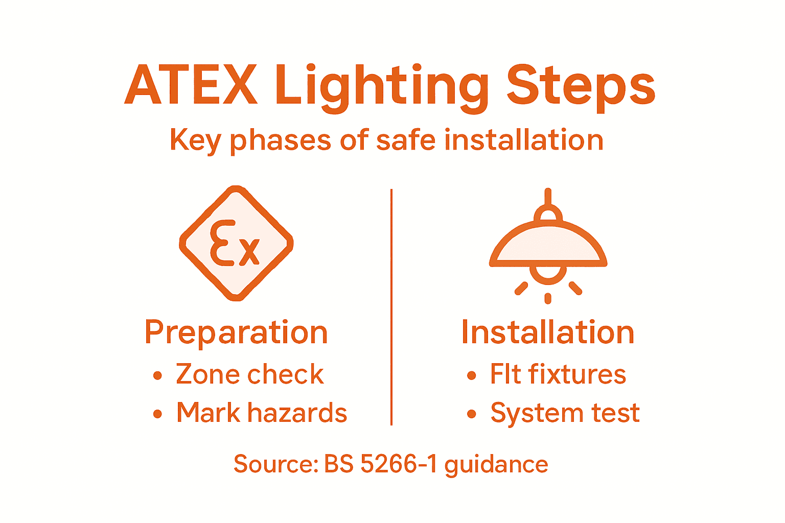
Start by identifying your hazardous areas. These aren’t always obvious. You might have explosive atmospheres only in specific zones—perhaps near chemical storage, paint spraying areas, or grain handling sections. A risk assessment following BS 5266-1 helps classify these zones by the type and mode of operation of your lighting systems, considering system integrity and failure modes.
Map out your premises and mark where hazards occur:
- Identify storage areas with flammable materials or vapours
- Locate production zones where explosive atmospheres might form during normal operation
- Note spaces where dust, gases, or vapours concentrate
- Mark any seasonal or occasional hazard areas (e.g., seasonal storage)
- Document areas with overlapping hazards
Next, assess your lighting requirements for each zone. Proper placement and selection of lighting types are essential parts of evaluating your needs. Consider illumination levels needed to prevent panic and enable safe evacuation.
Calculate lighting needs by evaluating:
- Minimum illumination levels required for safe movement and task visibility
- Escape route visibility and any obstacles or changes of direction
- Required colour rendering for accurate hazard identification
- Mounting heights and spacing to eliminate dark patches
- Backup lighting requirements for emergency scenarios
Your hazard assessment must determine whether emergency lighting is actually needed based on the size, function, and specific risk profile of your premises—not just assume every industrial space requires it.
Document everything. Create a simple record showing which zones are hazardous, what ATEX zone classification they have (Zone 1, Zone 2, etc.), and the specific lighting levels and types needed. This record becomes your baseline for equipment selection and installation planning.
Pro tip: Photograph your premises from multiple angles and annotate them with hazard zones and lighting placement notes. This visual record helps contractors understand your layout without visiting multiple times, reducing installation delays and costs.
Step 2: Select compliant ATEX lighting and components
Now that you understand your hazardous zones, you need to choose lighting equipment that actually complies with ATEX standards. This is where many facility managers stumble—picking cheaper non-compliant fixtures or mismatching equipment to zone classifications. The right selection prevents equipment failures, ensures worker safety, and keeps you compliant with UK regulations.
Understand ATEX protection concepts first. ATEX equipment must comply with European EN 60079 series standards, and each zone requires specific protection methods. The main concepts include Intrinsic Safety (safest, uses low energy), Flameproof enclosures (contain explosions), Increased Safety (eliminates ignition sources), and Pressurization (keeps hazardous atmospheres out).
Match your equipment to zone classification:
- Zone 0 or Zone 20 (explosive atmospheres continuously present) require Category 1G or 1D equipment only
- Zone 1 or Zone 21 (occasional explosive atmospheres) need Category 2G or 2D equipment minimum
- Zone 2 or Zone 22 (rare explosive atmospheres) can use Category 3G or 3D equipment
When selecting specific light fittings, verify three critical details. First, check the ATEX certification label on the fixture—it should show the protection concept, zone category, and gas/dust group. Second, confirm the equipment is certified for your specific hazardous atmosphere type (whether that’s petrol vapours, flour dust, or chemical gases).
Third, assess environmental suitability. Industrial spaces demand fixtures that resist corrosion, moisture ingress, and thermal stress. Choose stainless steel components for damp areas, sealed optics for dusty environments, and thermal management systems for high-temperature zones.
Selecting compliant ATEX lighting means matching equipment protection concepts to your zone classification and atmosphere type—mismatches leave dangerous gaps in safety.
Create a component checklist for your project. Document the zone classification, required ATEX category, protection concept needed, and specific atmospheric hazards (gas group, dust group). Use this checklist when evaluating suppliers and comparing quotations.
Also verify that ancillary components—emergency ballasts, surge protectors, and wiring—carry ATEX certification where required. Many installations fail because people upgrade one component whilst leaving non-compliant parts in place.
Here is a quick reference table classifying ATEX zones, equipment categories, and typical protection concepts:
| Zone Type | Minimum Equipment Category | Typical Protection Concept |
|---|---|---|
| Zone 0/20 (Continuous) | 1G/1D | Intrinsic Safety |
| Zone 1/21 (Occasional) | 2G/2D | Flameproof, Increased Safety |
| Zone 2/22 (Rare) | 3G/3D | Pressurisation, Encapsulation |
This table summarises the minimum compliance requirements for each hazardous zone type.
Pro tip: Request full technical documentation and ATEX certificates from your supplier before purchase, not after installation begins. This lets you verify compliance independently and prevents costly delays when site inspectors raise questions about equipment suitability.
Step 3: Prepare installation areas for safe fitting
Proper site preparation makes or breaks your installation. A poorly prepared area leads to delays, safety incidents, and incomplete work. You need to secure the space, communicate hazards clearly, and ensure your technicians can work safely whilst maintaining the integrity of your ATEX systems.
Start by reviewing your design plan and site layout. Confirm that access routes are clear, equipment can reach mounting locations, and workers have safe egress in emergencies. Remove obstacles, loose materials, or equipment that might interfere with installation work. This sounds basic, but cluttered spaces add hours to projects and increase accident risk.
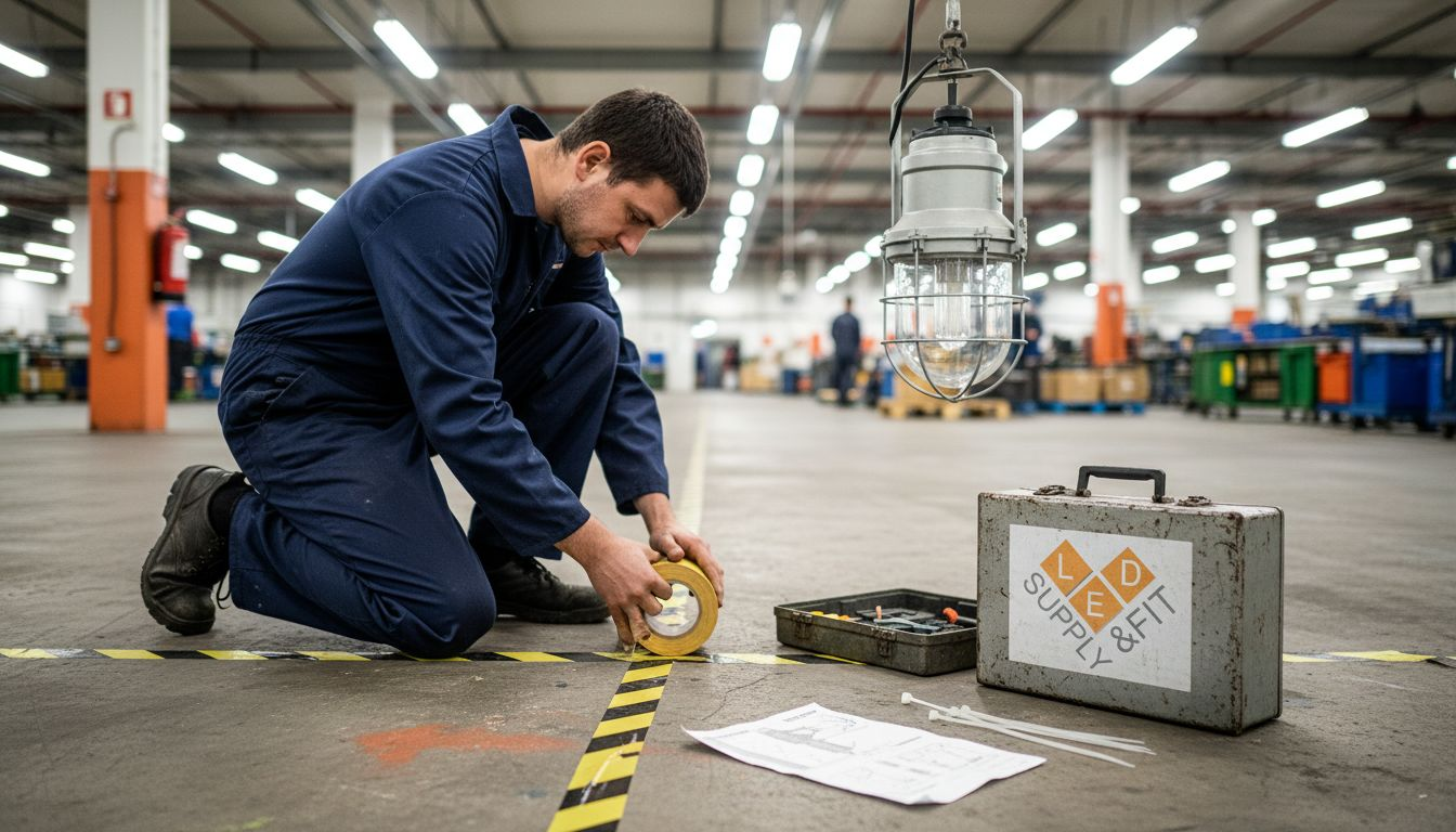
Mark hazardous zones visibly. Use yellow and black striped tape or hazard signs to identify areas where explosive atmospheres exist. This warning keeps non-essential personnel away and reminds installers which zones require ATEX precautions. Post clear notices explaining why zones are restricted.
Installation areas must be prepared according to the design plan, confirming the environment suits the lighting system type. This involves ensuring safe access, clear markings, and compliance with site safety regulations.
Prepare the specific work areas:
- Clear and clean mounting surfaces of dust, grease, and debris
- Test structural integrity of mounting points (walls, ceilings, poles)
- Verify electrical supply is isolated and locked out before work begins
- Set up temporary lighting if natural light is insufficient
- Establish a designated storage area for ATEX equipment away from contamination
Construction and site safety require hazard identification and risk assessments to prepare installation areas, minimising risks associated with working in hazardous environments. Document any site-specific hazards and brief your installation team on precautions.
Establish communication protocols. Designate a site coordinator who approves work before installation proceeds and checks each completed section. This prevents mistakes and ensures compliance throughout the project.
Never rush site preparation. The time you invest upfront prevents installation failures and keeps your team safe whilst maintaining ATEX system integrity.
Pro tip: Photograph your prepared installation areas before work begins, documenting baseline conditions and hazard markings. These photos provide evidence of proper preparation if regulators later question your installation process.
Step 4: Install ATEX lighting to UK standards
This is where your planning becomes reality. Proper installation determines whether your ATEX system actually protects workers and passes regulatory inspections. Follow the approved design plan precisely, and your installation will be safe, compliant, and durable.
Before touching any equipment, confirm your approved design plan is on site and all team members understand it. The plan specifies exactly where each luminaire goes, cable routes, connection points, and protection methods required. Install nothing differently than the plan specifies.
Start with the electrical isolation. Switch off and lock out the main power supply before any work begins. Use a lockout tagout system so no one accidentally restores power while technicians are working. This is non-negotiable in hazardous areas where electrical faults could ignite explosive atmospheres.
ATEX lighting installations must follow the approved design plan, ensuring compliance with BS 5266-1 and UK electrical safety standards such as BS 7671. This involves placing certified luminaires in correct hazardous zones and securing electrical connections with explosion-proof fittings.
Install luminaires step by step:
- Secure mounting brackets to the prepared surfaces using appropriate fixings
- Position each luminaire in the exact location specified on the design plan
- Connect wiring using only explosion-proof conduit and certified cable glands
- Ensure all connections are mechanically robust and electrically sound
- Verify that protection method integrity is maintained (flameproof seals, intrinsic safety barriers, etc.)
Maintain protection method integrity throughout installation. If your luminaires are flameproof rated, never leave enclosure doors open longer than necessary. If they use intrinsic safety, verify circuit components remain within certified parameters. One broken seal or incorrect component compromises the entire protection system.
Installation by qualified professionals following UK regulations ensures all wiring and fixing methods maintain the integrity of explosion protection ratings. Document each installation stage with photographs and notes.
Never deviate from the approved design plan. Even small changes can invalidate ATEX certification and create dangerous gaps in protection.
Test each luminaire before restoring power. Check mechanical security, verify cable connections are tight, and confirm visual indicators (pilot lights, etc.) function correctly. Only then should you restore electrical supply and commission the system.
Pro tip: Keep detailed installation records showing luminaire serial numbers, installation dates, cable runs, and connection configurations. These records prove your installation meets standards and are essential if the system ever needs modification or if inspectors audit your compliance.
Step 5: Verify and test completed ATEX lighting system
Your installation is physically complete, but the work isn’t finished until you’ve tested every component and verified compliance. Testing proves your system works under real conditions and meets regulatory requirements. Skipping this step leaves you exposed to safety failures and enforcement action.
Start with a visual inspection. Walk your installation and check every luminaire is properly mounted, all cable runs are secured, and enclosures are sealed correctly. Look for any physical damage, loose connections, or missing components that occurred during installation work.
Verify that illumination levels meet your design specifications. Use a calibrated light meter to measure brightness at key locations such as escape routes, work areas, and emergency exits. Compare readings against your approved design plan. If any area falls below specification, investigate and rectify the cause before proceeding.
Test system operation under normal conditions first. Turn on all luminaires and confirm they activate, illuminate to full brightness, and display any visual indicators correctly. Check that colour rendering is adequate for hazard identification in your specific environment.
Verification and testing involve commissioning the emergency lighting system post-installation, checking compliance with specified illuminance levels and system operation per BS 5266-1. Testing protocols include full system tests under failure modes to ensure lighting activates automatically.
Conduct failure mode testing:
- Simulate main power failure and verify backup systems activate within specified timeframes
- Test individual luminaire failure to confirm surrounding units maintain adequate coverage
- Verify that system faults trigger audible or visual alarms as designed
- Check backup battery duration meets or exceeds design specifications
- Confirm manual test switches operate correctly
Certified technicians conduct site surveys and test all luminaires for minimum three hours, assessing correct operation and compliance with safety standards. Document all test results with photographs and measurements.
Thorough testing now prevents failures that could leave workers in darkness during genuine emergencies, and proves regulatory compliance if inspectors visit your facility.
Obtain completion certificates from your certified technician. These certificates confirm your system meets BS 5266-1 and related standards. File these records alongside your design plan and installation documentation.
Schedule your first maintenance inspection within the timeframe specified by BS 5266-1, typically within one month of completion. This inspection catches any issues that emerged during initial operation.
Pro tip: Create a laminated testing schedule and post it near your ATEX lighting control panel, showing when routine tests are due and who performed the last inspection. This visible record demonstrates your commitment to compliance and helps team members understand why regular testing matters.
The table below compares key tasks and outcomes in each ATEX lighting installation stage:
| Step | Main Objective | Critical Documentation |
|---|---|---|
| Assessment | Identify hazards and lighting needs | Hazard zone map, lighting level plan |
| Selection | Specify compliant equipment | ATEX certificates, supplier records |
| Preparation | Ready site for safe work | Site prep log, risk assessment |
| Installation | Fit lighting to UK standards | Installation records, compliance notes |
| Testing | Prove system performance | Test results, completion certificates |
This overview helps ensure nothing is missed across the project lifespan.
Ensure Safe and Compliant ATEX Lighting with Expert Support
Navigating the complexities of ATEX lighting installation in hazardous UK environments can feel overwhelming. From understanding zone classifications to selecting the right certified equipment and following strict installation standards, every step demands precision and expertise. Avoid costly mistakes and safety risks by partnering with a trusted supplier who specialises in ATEX-rated lighting and professional installation tailored to your commercial premises.
Discover how Ledsupplyandfit.co.uk can simplify your lighting upgrade. Benefit from our extensive range of compliant ATEX lighting solutions, expert guidance on hazard assessments, and reliable installation services that strictly follow UK regulations. Whether you manage a warehouse, factory, or hazardous industrial space, we help you meet your obligations with confidence while maximising energy efficiency and long-term savings. Act now to secure cost-effective, high-quality lighting that protects your business and workforce. Explore our offerings online today and request your personalised consultation at Ledsupplyandfit.co.uk.
Frequently Asked Questions
What is the first step in the ATEX lighting installation process?
Before installing ATEX lighting, assess your premises to identify hazardous zones and specific lighting needs. Conduct a thorough risk assessment that highlights areas with flammable materials or explosive atmospheres, and create a documentation record of these zones.
How do I select compliant ATEX lighting for my installation?
Choose lighting equipment that meets ATEX standards based on the specific hazardous zone classifications. Ensure the chosen fixtures have the correct ATEX certification label, indicating safety performance and suitability for the identified hazards in your environment.
What preparations are necessary before installing ATEX lighting?
Prepare the installation areas by clearing any obstacles and marking hazardous zones distinctly. Ensure access routes are safe and that all personnel are briefed on site-specific hazards to maintain safety during the fitting process.
What steps should be taken during the installation of ATEX lighting?
Follow your approved design plan step-by-step without deviation to ensure compliance. Securely mount each luminaire using appropriate fixings, connect wiring with explosion-proof fittings, and verify integrity throughout the installation to maintain safety standards.
How can I verify that my ATEX lighting installation is compliant and functioning?
Conduct thorough testing post-installation to confirm that all lighting fixtures operate correctly under normal and emergency conditions. Use calibrated light meters for illumination checks, and simulate power failures to ensure backup systems activate as required, documenting all results.
What ongoing maintenance is recommended for ATEX lighting systems?
Schedule regular inspections according to the guidelines set forth in your installation documentation, typically within a month after completion. Maintain an inspection log that records each test date and results to ensure compliance and operational readiness.